Showing posts with label basic of HandPhone. Show all posts

Thursday, December 30, 2010

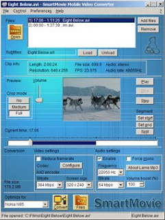
Smart movie new version 4.15 Cracked
,

Smart movie new version 4.15 Cracked


Play your videos on your mobile device,
anywhere, anytime, you need just a few steps

Convert any video file on your PC into a phone-friendly video file
Upload video into device/memory card
Play the video in SmartMovie Player installed on your mobile device
Features
Standard AVI format, allowing you to preview converted files on your PC
Also plays MP4V, FLV and 3GP file formats

Player uses the phone screen in
portrait or landscape mode, utilizing the full screen size of the device
Rescaling of video to utilize the full screen area
Support for subtitles - allowing you to watch movies in different languages
Friendly PC converter - preview videos on PC, select parts you want to convert, change conversion quality
Converter supports DirectShow codecs, so you may use video codecs downloadable from the internet
Fast conversion; on a standard PC conversion is 5x faster than the video clip playback time.
You'll convert entire movie in just a few minutes
Quality rescale algorithm in player, delivering best possible picture quality
Customizable video player (brightness, language, volume, and more)
User-friendly interface - watch movies, don't waste time configuring obscure settings
For full version use 4.01 keygen
smart movie 4.15 keygen
Smart movie 4.15 cracked

Friday, December 10, 2010

What is Phone Unlocking and How to Unlock a Mobile Phones

,
There are many mobile phones are "locked" into one particular service provider once purchased it. A user cannot use the handset to switch into another service provider by replacing available SIM card module into it.
So the best reason is to unlock the phone so it will be used into another network which is very useful when traveling from country to country.
Unlocking is completely legal and not illegal, because every phone user own the phone after all! 
the only reasons that the networks do it is to try to make sure that the phone users don't move to another network, but all it really does is stop them using the phone as they would like to!

But how to Unlock a Phone?

 There are two methods in unlocking mobile phones, It varies a certain products of mobile phones some can be easily unlock and some are not.
1. Unlocking by entering an unlock code. Many Nokia, Samsung, Siemens, Sony, Panasonic and some other brands of mobile phone will unlock if you enter a specific code based on your phone's IMEI (serial) number. This is the most easy method of unlocking - all you have to do is get hold of the code!
There are some that offers free unlock codes and some you need to purchased it via online.

2. If a model of phone does not support unlocking by code, you need to get the phone unlocked using a unlocking device and a unlocking software tool.

What is Flashing on Mobile Phones

,
Flashing is installing a new firmware to  a cellphone flash memory. When the cellphones firmware is being damaged or interrupted, this one particularly result on not powering the phone, hang up, or keep on re-starting and a lot more software problem issues.
This firmwares were comes with different versions.
 Each mobile phones product has unique firmware versions. And have also specific software that to be use for it.
If you have a basic computer knowledge is more advantage, but even if none you can still do and learn easily.
What things do we need in flashing cellphones?
In flashing phones we need ob-course
1.)A desktop or laptop computer to run the software program, with a USB (universal serial bus) port.
2.) Flashing Device- It is programmed circuit that can synchronize the mobile phone and the computer.
3. Flashing Software - this software is provided by the flashing device seller or even you can download it on the internet.
4. A USB cable and a flashing Cable wire- this the wire that used to connect the mobile phones to the flashing device that also connect to the computer.
This one is also provided by the flashing devices seller or you can purchased a pre designed one.
Every mobile phone products have different kinds of flashing devices used,  and also have different methods and procedures.
5. Flashfiles and Firmware collection- this are the programmed data used in the phones. See here of exmples of flashfiles in Nokia Mobile Phones.
Below are the list of Flashing devices which is being used to flash a certain and particular mobile phone products.

Advance-Box

Axe Box
Cruiser Team Products
CPF-box Products
Cyclonebox
Easy-Unlocker
ET-BoX
FuriouS TeaM Products
Genie Universal
GM-Box
GsmMagicBox G
SMServer Products
Infinity-Box
J.A.F - Just Another Flasher
Kulankendi Box / Dongle
Martech products
Mastertools
McnPro Box
Micro-Box.com Team Products
Multi-Box TEAM Products
MXKEY (by Alim Hape)
NEROkey
NSPRO
POLAR Team Products
Rocker Team products
T-BOX Products
SAGEM JTAG UNLOCKER
Saras Boxes
SMTi Support Sections
SpiderMan
SPT BOX
Super Doctor Box (MTK-BOX)
TEST-BOX 2
TGT Products
Ultimate-Sam
Universalbox
UST Pro II
Ve Box
Vodafone Star
VygisToolbox
Z3X-Team Products

Power ON OFF Switch on Mobile Phone - Test and Check Up Procedures

,
ON/OFF Switch on cell phones comes different  varieties and forms or designs but the fundamentals on how does it work or where to use it is the same. On Off switch can be determine by the number of its legs or terminals.
This cell phone repair tutorial for beginners covers on how to check the power on off switch on mobile phones and also work on  volume key switches. 

Here's a brief information on every ON and OFF switch which covers how the components being assembled and by this information you can easily test and check up the said switch if it is good or in working condition.

By checking on off switch is been so simply by just only checking its terminals conducting continuity.
A broken power on off switch can be easily determine when its visual assembly is busted out,
so this procedure below covers only when the said switch visual assembly seems to be good.

This also the first step to repair the mobile phone if unable to power up, its like happens when the phone can accept and show charging if at charging state but unable to power up while pressing the power ON OFF button switch.


The two Legs On OFF switch assembly:

This check up procedure can work even if the ON OFF switch is mounted on the printed circuit board or isolated.
Two check this two legged kind of ON OFF switch is  by simply set the multimeter to X1, then connect the two test probes of the multimeter to both legs of the switch, we are  just simply trying to check here if the on off switch continuity. Then hold it so that it won't move then simply press it gently. You can easily determine it here when the said switch is working or not by the multimeter response, If the pointer moves approximately 0ohms the switch is good and working, but while if it is not moving at all it means the switch is faulty.

The four legs ON OFF switch assembly:


This check up procedure can work even if the ON OFF switch is mounted on the printed circuit board or isolated.
Four legged On off switch has its both opposite two terminal connected which other, so by checking this said switch is similar to the two legged on off switch. Again. just set the multimeter to X1 and connect the both probes to both opposite terminal of the said switch then simply hold and gently press it to get readings.
If the the multimeter's pointer moves it means  it is working while if not the switch is faulty.

Read here for  understanding how ON OFF switch works for advance power ON OFF switch problem repair troubleshooting techniques.

How to check Mobile Phone Battery Voltage

,
A good and working battery voltage is approximately 3.7 volts DC(direct current),  below that maximum voltage range the phone will not be able to power on.
Checking the battery voltage by an analog multi-meter is so easy, just set  it to a DC range 10volts then attach the both test probes to each corresponding polarity, positive probe to positive terminal, then negative probe to negative battery terminal. Check the maximum battery voltage reading  3.7 volts.
A battery voltage lower than 3.7 volts can power on the handsets but it shows Battery Low on a screen.
A battery voltage lower than 2 to zero volts will hardly charge the phone and won't power up the phone.

A drain battery voltage approximately down to zero volts will not be able to accept charge when a charger is being plug-in. A drain battery will be
shock by a a higher voltage range from 6 to 12 volts for a quick charging point as possible to avoid damaging the battery,  a DC regulated power supply. is the equipment used to shock a drained battery.just connect both probe to each corresponding polarity for a quicker period of time, prolonging it will damage the battery itself. You may ask an experience technician in your neighborhood about this method for assistance and safety guidelines.

How to Test Mobile Phone Vibration Motor

,
A mobile phone vibration is created by a small motor called Vibra motor. when applied by a voltage or current it rotates and the vibration is generated by a small tiny piece of metal attach to its tip.

Mobile phone vibrator motor

Checking this small piece of motor was so very easy just set the analog multi-tester range to X1 in resistance
 settings then connect the both probes to each terminals, polarity doesn't matter here for the motor will rotate clockwise if its in the right polarity. and rotates counter clockwise when not in each corresponding polarity.
A good and working vibration motor will then rotate and a bad or busted one will not.

How to test Mobile Phone Charger Voltage

,
Learning to check mobile phone charger voltage is also a big help when it comes to troubleshooting charging problem.
Various mobile phones have different varieties of charger packaging and designed but almost all of them have one the same operational concepts.

A picture below is an example of a charger used in Nokia Mobile Phones.
The concepts is that the positive voltage is in the inner side of the connector pin while the negative voltage is in outer side of the pin. Charger voltage range from 4.5 to 6 volts and an average rating of 800 milliAmpere current.
Checking it output voltage will be on its connector pin tips. Just set the analog or digital multi-meter to 10DCV or higher range. and connect both test probe to its corresponding polarities. A good and working charger will get the approximately correct reading while the busted one will get no reading.

Many experts know how to fix mobile phone charger for they know the whole designed of its circuitry inside it, but I'd rather not encourage to the newbies to teach about it because it is so complicated and might result risk of electric shock or any possible accident. It is because that circuit involves AC (alternating current) on it, NOTE: Alternating Current is a dangerous voltage and can kill if not have much knowledge about it.

How to Test Mobile phone Speaker,Buzzer or Ringer

,
Speakers also known as earpiece is the device that allows the handset user to hear the other user during call convesations.
While the
Buzzer or a Ringer is the one that sends out the ringtone to be heared by the handset user.
Both Earpiece, buzzer or ringer are same speaker. it only varies the loudness of it sounds being produce.
Ringer buzzer generates more loudness than the earpiece speaker.
A speaker is a device that  converts electrical signal into sounds.
It is made by a magnetic wire winded into a coil and a metal piece of magnet.
below is an example oh how to test of a good and working speakers .

Simply set the analog or digital multi-tester to X1 resistance value, and attach one probe to one the speakers terminal while tick tacking the other one unto it.
A working speaker produce a crackling sounds and the multi-tester pointer moves, while the a busted one will not and have no reading.

What is RAM IC ? how does it work on mobile phones handsets

,
Random access memory (RAM) is used in mobile phones circuit to store memory datas. It is made of millions of transistors and capacitors that being packed into integrated circuit (IC)
Transistors and capacitors are paired to create a memory cell, which represent a single bit of data. The capacitor holds the bit data of information, a 0 or a 1. The transistor acts as a switch that lets the controlcircuitry on the memory chip read the capacitor or cahnge its state. In most cases common form of mobile phones memory is a Dynamic random access memory (DRAM)
The opposite of RAM is Serial Dynamic Random access memory (SAM). SAM stores data
as a series of memory cell that can only be access sequentially. If the data is not in the current location each memory cell is check until the needed data is found.


SDRAM
SDRAM stands for Synchronous Dynamic Random Access Memory. DDR is short for "DDR SDRAM" and stands for Double Data Rate. Nowadays to avoid misunderstandings SDRAM is often specified as SDR SDRAM and SDR stands for Single Data Rate by analogy with DDR. Therefore, the main difference between SDR and DDR memory the doubled speed: DDR can transfer data at roughly twice the speed of SDRAM.

DRAM. Dynamic Random Access Memory is used to temporarily store information on mobile phones. DRAM is made up of many cells and each cell is referred to as a bit. A cell contains a capacitor and a transistor. Since computer machine language is made up of 1s and 0s, it has the value of one when active and zero when inactive.
SDRAM or Synchronous Random Access Memory is the result of DRAM evolution. This type of memory synchronizes the input and output signals with the system board. Its speed ratings are in MHz. SDRAM was introduced in 1996 and is still used today. SDRAM transmits every clock count at a specific time.
DDR RAM (or Double Data Rate Random Access Memory) does the same but it does so twice every clock count. This makes DDR RAM twice as fast as SDRAM.

What is NAND and NOR Flash Memories

,
There are two types of flash memory, NOR and NAND. The names refer to the type of logic gate used in each memory cell. (Logic gates are a fundamental building block of digital circuits). NOR flash memory was first introduced by Intel in 1988. NAND flash was introduced by Toshiba in 1989
The two chips work differently. NOR flash is faster, but it's also more expensive and takes longer to erase and write new data. NOR is most often used in mobile phones. NAND has significantly higher storage capacity than NOR. It has found a market in devices to which large files are frequently uploaded and replaced. MP3 players, digital cameras and USB drives use NAND flash.
NAND Flash is a special form of Flash memory. Flash memory is a memory technology that keeps data even when the power supply is cut off; this is known as a non-volatile memory type. Flash memory can be read pretty fast, but writing to Flash memory is pretty slow compared to many other -volatile- memory technologies such as SRAM or DRAM. Flash also has a limited number of write-cycles; manufacturers typically specify something in the area of 10,000 writes for the lifetime of the part.
NAND Flash is faster than regular Flash, although the general characteristics still hold.
Flash memory is widely used in digital cameras, portable MP3 players, USB (Flash) sticks, and many other devices.

NOR flash memory is a type of non-volatile storage technology that does not require power to retain data.
NAND devices are accessed serially, using the same eight pins to transmit control, addressing and data. NOR flash memory supports one-byte random access, which allows machine instructions to be retrieved and run directly from the chip, in the same way that a traditional computer will retrieve instructions directly from main memory. NOR flash has an SRAM interface that includes enough address pins to map the entire chip, enabling for access to every byte stored within it.

Some devices use both NAND and NOR. A pocket PC, for instance, may use embedded NOR to boot up the operating system and a removable NAND card for all its other memory or storage requirements.

What is An Application Processor in Mobile Phones Circuit Do

,
An application processor is a central proccessing unit (CPU) like the one installed on personal computer. It is the brain and controls all kind of data and information any application in mobile phones circuit.
It is microprocessor integrated circuit (IC) chip.

 LCD controller, camera interface, serial interfaces, memory interface,USB  controller, bluetooth and wifi controller,and more. are controlled by an the application processor.

Here's an example of an application processor block diagram below, on how this kind of IC works on mobile phones circuit. This kind of  an application is commonly used on Nokia latest designed of mobile handsets. The description of this application processor below will help us understand how does this certain IC work.
omap block diagram

OMAP2420 Processor

The OMAP2420 processor is a single-chip applications processor that supports all cellular standards, and complements any modem or chipset and any air interface. It is intended for high-volume wireless handset manufacturers and is not available through distributors. The OMAP2420 includes the benefits of the OMAP 2 architecture’s parallel processing, giving users the ability to instantly run applications and operate multiple functions simultaneously without quality of service compromises. The OMAP2420 includes an integrated ARM1136 processor (330 MHz), a TI TMS320C55x™DSP (220 MHz), 2D/3D graphics accelerator, imaging and video accelerator, high-performance system interconnects and industry-standard peripherals.
Graphics

The OMAP2420 processor embeds Imagination Technologies' POWERVR MBX™ graphics core, making it the first applications processor to support OpenGL ES® 1.1 and OpenVG™, providing superior graphics performance and advanced user interface capabilities. TI is enabling sophisticated and dynamic images with "smart pixel" technology offered via OpenGL ES 1.1. This unique technology allows each pixel in an image to be programmed individually, giving developers the power to create rich effects with cinematic realism. Users will now experience "life-like" facial features, advanced reflection effects and multi-textured backgrounds in the mobile environment.

Multimedia enhancements made in the OMAP2420 include an added imaging and video accelerator for higher-resolution still capture applications, multi-megapixel cameras and full-motion video encode and decode with VGA resolution of 30 frames per second. An added TV video output supports connections to television displays for displaying images and video captured from the handset. 5-Mb internal SRAM also boost streaming media performance. Access to the OMAP Developer Network also provides an extensive range of programs and media components that manufacturers can use for differentiating and delivering products to market fast.

Key Features:

  • Dedicated 2D/3D graphics accelerator at 2 million polygons per second
  • Added imaging and video accelerator enables high-resolution still image capture, larger screen sizes and higher video frame rates
  • Supports high-end features including 4+ megapixel cameras, VGA-quality video, high-end interactive gaming functionality and analog/digital TV video output
  • 5-Mb internal SRAM boosts streaming media performance
  • Software compatibility with previous OMAP processors
  • Parallel processing ensures no interruptions or degradation of service with simultaneously running applications
  • Optimized power management companion chip, TWL92230 12 mm x 12 mm, 325-ball MicroStar BGA™, 0.5-mm pitch

What is Power Mangement IC, How Does it supply power voltage to a Mobile Phones circuit

,
Power Management IC is a power IC, that manage,control and distribute and Supply Power voltages from the battery source to other corresponding circuits or chips.
It is highly designed to convert,regulate, stabilize current and voltages that flow across unto it.
A power supply IC Chips can divide and multiply certain voltage from one desired voltage source to any desired power output voltages.
Which is for example a battery voltage source  amounts at 3.7voltsDC while other components chips or circuit only requires the amount of 1.8volts, This 1.8volts  is the amount of voltage is what the power management IC are going to convert.
A block diagram below shows a brief details on how power supply IC converts and distribute certain desired
voltage from a battery power source to other corresponding circuits or components.
In a typical schematic diagram like in Nokia mobile phones, certain output supply power voltages were labeled as how much the amount of each output to supply power voltages to another circuits or components.
A failure of a power management IC to gain this following output voltage is also a failure to other corresponding components or circuits to work.
A picture below is an example layout of a power management IC mounted on a printed circuit board.
A deep familiarization of how this chips works including  its whole operation within a circuitry of mobile phones is  also a powerful tool in troubleshooting hardware problem issues on a mobile phones.

Familarization: Components and Parts on Nokia Mobile Phone Handsets

,
This is an example of Nokia Mobile Phone Handsets Components and Parts Descriptions, including the manufacturers on each and every chips mounted and used the entire circuitry.
Knowing and understanding in each and every components and parts is a big help on Hardware Fault Finding and Trouble shooting.


The N95 is part of Nokia's N-series of handsets, focusing on delivering multimedia content. It was previously the flagship model of Nokia's entire handset lineup, predecessor to the current flagship, the Nokia N96.


Nokia N95 Models

Nokia N95-1 External MicroSD Slot, 3G for Europe
Nokia N95-2 Internal 8GB Memory, 3G for Europe
Nokia N95-3 External MicroSD Slot, 3G for North America
Nokia N95-4 Internal 8GB Memory, 3G for North America


Product Features & Specifications


Technical Specifications

Operating System Symbian OS 9.2, S60 rel 3.1
Network Support GSM/GPRS/EDGE/HSDPA, UMTS: 850/2100, GSM: 850/900/1800/1900MHz
Screen 2.6" QVGA (240 x 320px), 16M Color TFT
Input Method Slide-out Numeric Keypad, Slide-out Multimedia buttons
Wi-Fi 802.11b/g, UPnP support
GPS Internal GPS with A-GPS
Bluetooth Bluetooth v2.0, A2DP support
Camera 5.0MP Camera with Carl Zeiss optics, Auto Focus, LED Flash; Secondary CIF Front Camera
Storage Internal 160MB Storage, External MicroSD Slot; OR Internal 8GB Storage
Connection Ports Mini-USB 2.0 Hi-Speed, 3.5mm stereo audio jack w/ TV-out
Physical Attributes Dimension: 99mm x 53mm x 21mm, Weight: 120g

Media Support

Audio Support Codecs: MP3/WMA/AAC+/eAAC+/M4A/Real Audio


Bill of Materials

* The following bill of materials is taken from an N95-1 model

Processor Texas Instruments #4377454 Baseband Processor (Unmarked)

Texas Instruments OMAP2420 Applications Processor (ARM11 Core @ 332MHz)
Storage Samsung K5W2G13ACM-DK60 MCP - 2Gb OneNAND, 512Mb Mobile DRAM

Samsung K4M28163PH-KG750 MCP - 128Mb Mobile SDRAM

Spansion S72NS128NDOAJW13 MCP - 128Mb NOR, 128Mb DDR DRAM
MicroSD Interface NXP IP4352CX24LF
Camera Micron Technology MT9P001 (5.0MP Image Sensor)
Wi-Fi STMicroelectronics STLC4550 #4396287-1 (Unmarked)
GPS Texas Instruments GPS5300
Bluetooth CSR BlueCore4 BC41B141B
Infrared Vishay TFBS5700-TR3
Audio Texas Instruments TPA4411YZHR
FM Radio Tuner NXP Semiconductors TEA5761UK
Accelerometer STMicroelectronics LIS302DlTR
RF Transceiver STMicroelectronics #4380206 Quad-band GSM/GPRS/EDGE, Dual-band UMTS/HSPDA (Unmarked)
Power Management PMIC: Texas Instruments TWL92230CZQE

STMicroelectronics #4396299 (Analog Baseband/Pwr Mgmt) & #4376535 (Batt Charger) (Unmarked)

Power Amp (RF) : RF Micro Devices #4355951 (GSM) & #4355898 (UMTS) (Unmarked)

Power Amp (Wi-Fi): RF Micro Devices RF5924

Power Amp (Audio): Texas Instruments TPA2012D2YZHR


Block Diagram


Teardown Pictures


How To Solder SMD Components Manually by Hand

,
Proper Soldering and De-soldering Methods and Techniques on Surface Mount Components

Soldering is the process of using a metal alloy with a low melting temperature (solder) to Fuse the the electrical contacts of a component to the pads of a circuit board. Proper soldering maximizes the strength and conductivity of the connection. Poor soldering can result in weak connections, higher resistance that causes heat buildup at the connection, and possible failure of the component.


The type of components and the pads to which they will be attached dictate the appropriate soldering method. The correct amount and duration of heat to be applied is a function of the heat transfer characteristics of the component, the circuit board, the solder pads, the solder and flux, and the environment, in which the soldering takes place. For this reason, effective soldering requires reasonably controlled. Some experimentation is usually required to determine the optimal conditions for each application.


General Soldering Guides

All soldering applications require the following considerations:
*
Preparation - Clean connections are essential to soldering. Clean connection maximize the ability of the solder to adhere uniformly to the joint surfaces ((welting).
*
Soldering Method - The component type and size and your specific application determine the soldering method.
*
Materials Selection - The component contacts, circuit board pads, solder,and flux materials must be compatible with soldering method.
*
Maximum Temperature - The soldering materials and method determine the temperature profile. All components must be able to withstand the maximum exposure temperature of the soldering operation for specified time and duration.

Manual (Hand) Soldering Technique

While the amount of solder, and the amount and duration of heat to be applied are application-specific, the following general hand-soldering guidelines will lead to consistent and reliable solder connections. A hot air gun is proffered for even heat application and control. The following techniques applies to hand soldering of surface mount components using solder wires and soldering iron.

Preparation

Before beginning to the soldering process, identify the solder composition
and flux type. The solder type dictates the appropriate temperature of the soldering iron tips. Use small diameter wire solder for soldering small SMT components.
Select an appropriate size tip before heating the soldering iron for a fine work result. Clean the tip of any oxidation or contamination. Place a sponge soaked in cold water, nearby for frequent tip cleaning between soldering operations.
Clean the electronic component's contact/leads and the circuit board pads of any contamination or residue.


Hot Air Gun and Soldering Iron Temperature Settings

Hot air temperature temperature tends to be variable when working on any SMD components various Mobile Phones Products used different kinds of solders, check the manufacturer recomendations for specific solder types. The solder manufacturer may only provide the melting temperature range, so you may have to experiment to determine the appropriate temperature.
The amount temperature on Hot Air gun commonly setting is between 250-350 degrees Celsius.
While soldering iron is between 200 to 280 degree Celsius.


This procedure covers the general guidelines for soldering surface mount chip components. The following surface mount chip components are covered by this procedure. While all of these components are different, the techniques for soldering are relatively similar
 
Chip Resistors
The component body of chip resistors is made out of alumna; an extremely hard, white colored material. The resistive material is normally located on the top. Chip resistors are usually mounted with the resistive element facing upwards to help dissipate heat.


Ceramic Capacitors
These components are constructed from several layers of ceramic with internal metallized layers. Because metal heats up much faster than ceramic, ceramic capacitors need to be heated slowly to avoid internal separations between the ceramic and the metal layers. Internal damage will not generally be visible, since any cracks will be inside the ceramic body of the component.

NOTE

Avoid rapid heating of ceramic chip capacitors during soldering operations.

.
Plastic Body
Another style of chip component has a molded plastic body that protects the internal circuitry. There are a number of different types of components that share this type of exterior package. The termination styles for plastic chip component packages vary considerably.

MELF

MELF - Metal Electrode Face cylindrical components. These may be capacitors, resistors, and diodes. It can be hard to tell them apart - since there is no universal coloring or component designators printed on the component bodies.


Replacing SMD Component on Printed Circuit Board 
De-soldering and Soldering Hand Method
TOOLS & MATERIALS
Cleaner
Flux
Microscope or Magnifying Glass lamp
Solder
Soldering Iron with Tips
Rework Station Hot Air
Wipes
PROCEDURES  TO REMOVE SMD COMPONENT
Add liquid flux to both terminal pad.
Photobucket
Photobucket
Apply Desired Amount of heat on both sides of the leads.
Photobucket
Photobucket
Use a Tweezer to hold the component and observed until the solder joint is melted.
Photobucket
Slowly pull in upward direction, when solders are already melted. do not pull upward forcibly when the solder is not melted yet. You might end up lifted the the terminal surface pads.
Photobucket
 Photobucket

PROCEDURE TO REPLACE SMD COMPONENT
Clean the surface terminal pads with cleaning kits.Removed remaining old solders by using solder wick
Photobucket
Photobucket
When the pads is cleaned, Apply adequate amount of flux into the pads.
Photobucket
Photobucket
Then apply both pads with fresh solder with desired heat controlled soldering iron.
Photobucket
Photobucket
Place the component in position and hold it steady with a  tweezers so that the hot air won't push the component out of alignment.
Photobucket
Tack it down and apply heat
Photobucket
Wait a moment for the solder to solidify both leads terminal.
Photobucket
Remove heat and hold the SMD components with tweezer until the heats out and  cool.
Photobucket
Cleaned the surrounding  areas with cleaning kit.
Photobucket

You can practice by doing this with an old and non working cellphone PC Board. The more you do practice the more you will master it. Also observed and always become familiar of Hot air and soldering iron   temperature settings. In my experience various type of cellphones solders have different melting point of the solder leads. There are too soft and there are also hard soldered leads to removed.

How to Find Component Parts on PCB Board?

,
How to Find Component Parts on PCB Board?

A certain components parts is easy to find with an aide of schematic diagrams. In Nokia Phones finding it was been so easy for they provide a complete and accurate component data on their Schematic Diagrams. While other various mobile phone don't have. Some cellphone technicians find it hard to fix some of mobile phone products for they don't provide schematic diagrams to be available, but many experts and masters can do the job even without schematic diagrams. Experts can rely on their deep knowledge on electronics components and circuits, many of them where electronic engineers and also many of them where professionally skilled by experience and mastered for years. You can be one of them if you follow their instinct but before that they all started from scratch.We are all start from scratch.


Now, let's take up a very simple method on how to find certain electronic component's location  where it is being mounted on a particular PCB Board layouts.

Here's an example of Nokia N70 schematic diagram, Download it here if you haven't a copy yet, and make sure you have Adobe Reader installed on your computer to be able to open it.
If you already  have a copy of this schematic diagram,  open it and scroll it down to the bottom page.
In the bottom page which is the last page you may found this
Component Finder Page. see picture below:
Photobucket

On the right side you may find the table of components which is listed in codes like for example, Resistors starts with letter "R" then "mounting code" . next to it on the left is the "
pattern codes" which is means the spot point which is scaled by letters and numbers on the PC Board,

Photobucket

On the right side of the page is the layout of all of components with respective
codes mark on it. Each component mounted in horizontal and vertical positions.
Photobucket

In both sides on the PCB layout is being scaled by letters and numbers, this is were the
pattern codes from the first picture above being produce by combining the letter and number to make the mapping spot point.
The
spot point of where these letter and number meets across each other, is the exact location where that certain component is being mounted.
Photobucket

Now let's take a little bit exercise on how to use this methods..

Okay, assuming that we are looking for a certain components on a PCB board.
Let say that we are going to find the 2n2 valued capacitor on RF Section for that phone is having a problem of network signal.

now scroll up the page to RF Section which is on page 9 and find these two 2n2 (2.2nanofarad) valued capacitor 
see guide picture below;  Just remember and get the Mounting Code for it is the code were going to use as a guide to to the component finder table of components.

Photobucket


Then after finding it scroll back to the Component Finder page Table of components, then find it on the lists of the components codes like "C7524 is on B9" and "C7573 is on A6"


Photobucket


the next thing again you have to do is to remember and get that code then proceed to the Component Layouts. and scale the spot point of  "letter B and 9" then letter "A and 6" on the scaled on the opposite sides.
See picture below
Photobucket

The last part is to scroll it up on the whole component layout on the upper page 10 or on your PC board then spot and mark that component where it is being mounted.

Photobucket

There you go you just found it! congratulation!

Practice it more often,so that you can be familiarize on each component or parts for that certain product. The more often you do it, the more chances you will mastered it. sooner,you can work it alone without even using the schematic diagram anymore.
 

Mr.Mobile Copyright © 2011 | Template design by O Pregador | Powered by Blogger Templates